


NexCAD
Introduction
Every error on this list has caused real production failures, real scrap costs, and real supplier disputes. Here is what they are, why they happen, and exactly how AI drawing checkers find them automatically.
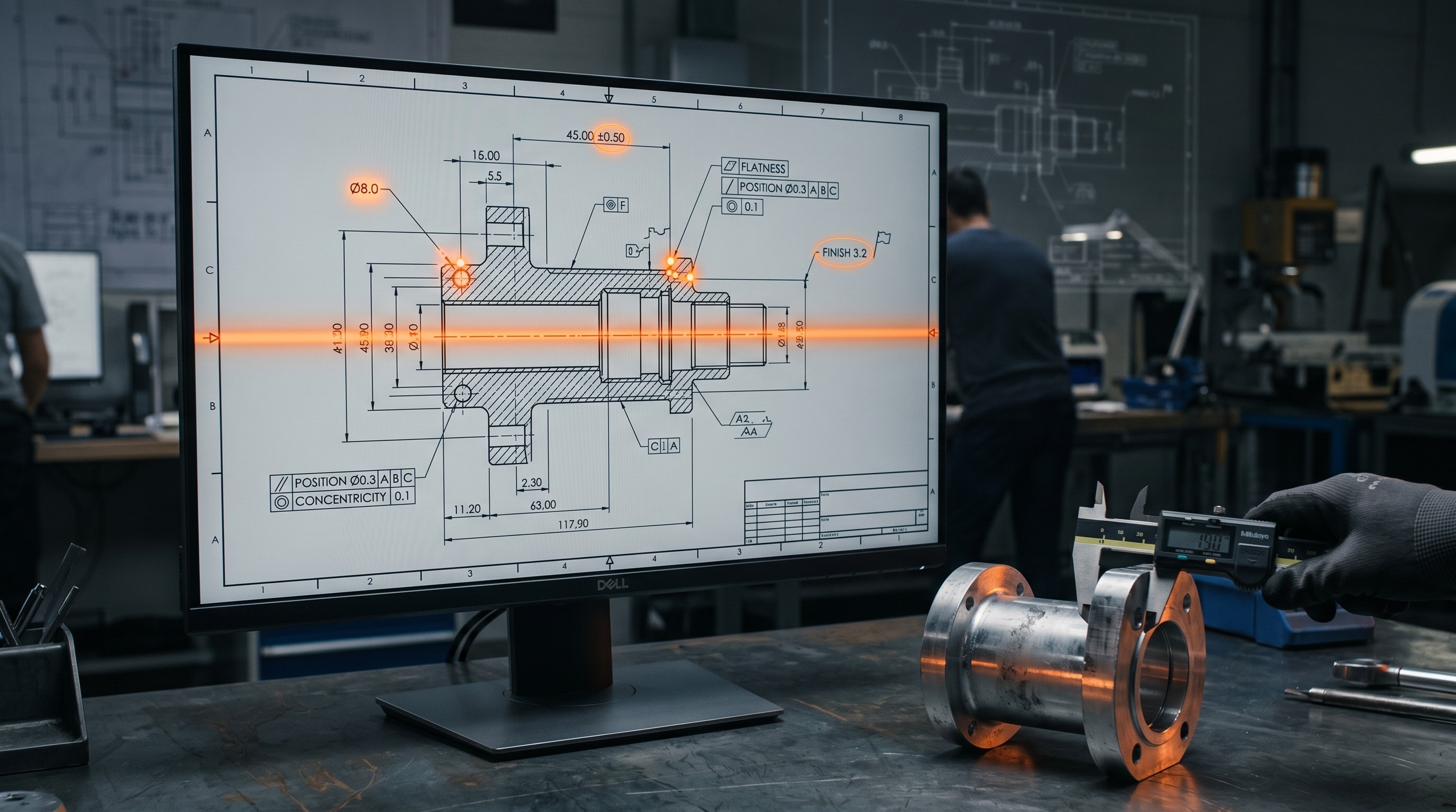
Common engineering drawing errors that lead to production failures — identified automatically through AI-based review.
15%of errors in a drawing set survive manual review and are discovered downstream in production | 92%precision achieved by NexCAD AI on core drawing checks in under 60 seconds per drawing | $50K+average rework cost per production cycle from drawing errors that slip through manual review | 100×more expensive to fix a drawing error after production than to catch it at design review stage |
Engineering drawings are the contract between design intent and manufactured reality. Every dimension, every tolerance, every note on a released drawing becomes a specification that a machinist, a supplier, or an inspector will act on — without knowing what you meant. They will only know what you wrote.
Drawing errors are not rare edge cases. Based on NexCAD's analysis of over 2,500 engineering drawings reviewed by AI, the vast majority of drawing sets contain at least one error that would survive a manual review. The most dangerous errors are not obvious typos — they are ambiguities, missing callouts, and standard violations that look correct to a tired reviewer but create catastrophic ambiguity at the shop floor.
This article documents the 10 most common engineering drawing errors found by AI drawing checkers, with the real manufacturing consequence of each and an explanation of exactly how AI detects them where manual review frequently fails.
Quick reference: all 10 errors at a glance
Use this table to identify which errors are most relevant to your drawing set, your industry, and your risk profile. Detailed analysis of each error follows below.
# | Error type | Where AI catches it | Severity | Consequence if missed |
|---|---|---|---|---|
01 | Missing or incomplete dimensions | Geometry vs. dimension cross-check | Critical | Part returned from supplier — under-constrained geometry cannot be machined to spec |
02 | Incorrect or missing GD&T callouts | GD&T compliance checker | Critical | Parts pass inspection but fail assembly — functional failure with no obvious cause |
03 | Undeclared or wrong drawing standard | Title block validator | Critical | Cross-standard misinterpretation — supplier builds to wrong specification |
04 | Incomplete or wrong title block data | Title block field validator | High | Wrong revision released; procurement orders wrong material; audit non-conformance |
05 | Tolerance stack-up conflicts | Cross-feature tolerance analyser | Critical | Assembly fails — parts in-tolerance individually but impossible to assemble |
06 | Over-tight or arbitrary tolerances | DFM risk detector | High | 2–3× manufacturing cost increase with no functional benefit; excess scrap |
07 | Wrong or missing projection angle | Projection symbol checker | Critical | Mirror-image manufacturing — complete batch scrapped, caught only at assembly |
08 | Ambiguous or conflicting notes | Notes consistency checker | High | Supplier interprets note incorrectly; non-conformance found after delivery |
09 | Missing or incorrect surface finish | Callout completeness checker | Medium | Wrong roughness on sealing or bearing surfaces — functional failure in service |
10 | Cross-sheet dimension mismatches | Multi-sheet consistency checker | High | Mixed production batch — some parts built to old value, some to new |
The 10 errors in detail
01 | Missing or Incomplete Dimensions
|
|---|
What it is | Why it matters | How NexCAD AI catches it | Prevention rule |
A feature — hole, slot, boss, radius, chamfer, pocket depth — appears in the drawing geometry but has no dimension callout controlling its size, location, or both. The feature exists visually but is undefined metrologically. | The machinist cannot proceed from an undimensioned feature without making an assumption. Every assumption is a potential non-conformance. Under-constrained geometry is the most common root cause of supplier RFIs and the most common reason a drawing is returned before production begins. | NexCAD's vision AI reads the drawing geometry and cross-references every visible feature against its dimension callouts. Features that appear in any view but lack a controlling dimension are flagged with a bounding box at the feature location, identifying the feature type and the specific dimensions missing. | Use a drawing completeness checklist before release: every feature that appears in any view must have at least one controlling dimension. Run AI first-pass immediately after the drafter completes the drawing — catching missing dimensions here takes 2 minutes; catching them at the supplier takes 2 weeks. |
02 | Incorrect or Missing GD&T Callouts
|
|---|
What it is | Why it matters | How NexCAD AI catches it | Prevention rule |
GD&T errors fall into two categories: missing callouts (a feature requiring geometric control has none, relying only on general tolerance) and incorrect callouts (wrong feature control frame format, deprecated symbols, incomplete datum references, or modifiers applied to the wrong feature type). | A missing GD&T callout on a functional feature — mating surface, bearing bore, alignment pin — means it is controlled only by ± coordinate dimensions, creating a square tolerance zone instead of the cylindrical zone that reflects function. Parts can pass inspection and fail assembly. Incorrect callouts, particularly concentricity (◎) on ASME Y14.5-2018 drawings, create callouts with no valid interpretation. | NexCAD validates every GD&T callout against the standard declared in the title block. For ASME Y14.5-2018: flags concentricity and symmetry symbols (removed in 2018), incomplete feature control frames, datum reference frame inconsistencies across sheets, and profile tolerance completeness. Each finding identifies the specific rule violated and the standard section governing it. | Establish a GD&T callout policy: which features always require explicit geometric control (bearing bores, mating planes, hole patterns). Train your team on ASME Y14.5-2018 changes if they were trained on the 2009 edition — the removed symbols are the most common source of cross-standard non-conformances in 2025–2026. |
03 | Undeclared or Wrong Drawing Standard
|
|---|
What it is | Why it matters | How NexCAD AI catches it | Prevention rule |
The drawing does not state which GD&T or drawing standard governs its interpretation — or it states a standard that conflicts with the symbols used on the drawing itself. Most common: no standard reference in the title block. | Without a declared standard, every GD&T callout is ambiguous. The Envelope Principle (ASME default) and the Independency Principle (ISO/BS8888 default) interpret the same dimension differently. For regulated industries — aerospace, medical, defence — an undeclared drawing standard is a direct audit non-conformance against ISO 9001, AS9100, and IATF 16949. | NexCAD reads the title block and notes block for a declared standard reference. If none is found: critical finding — 'No drawing standard declared — interpretation is ambiguous.' If a standard is found but symbols are inconsistent with it, NexCAD raises a conflict finding identifying both the declared standard and the non-conforming element. | Make standard declaration mandatory in your drawing template. Add a locked field in your title block that requires 'ASME Y14.5-2018' or 'BS8888:2025' before the drawing can be released. This is a 30-second template change that eliminates an entire category of supplier disputes. |
04 | Incomplete or Wrong Title Block Data
|
|---|
What it is | Why it matters | How NexCAD AI catches it | Prevention rule |
One or more required title block fields are blank, inconsistent, or incorrect. Common missing fields: material specification (grade, condition, standard), revision level, projection angle symbol, drawing number, part name. Common incorrect data: revision level mismatched to ECR system, scale inconsistent with drawing views. | An incomplete title block creates immediate downstream problems. A missing material specification means procurement orders a default — which may have the wrong strength, corrosion resistance, or machinability. A wrong revision level means the supplier manufactures from a previous iteration. In quality audits, an incomplete title block on a released drawing is a non-conformance against every major QMS standard. | NexCAD reads title block fields and validates them against a configurable required-fields list. For each field it checks: (a) is it populated?, (b) does the value match the expected format?, (c) is it consistent with drawing content? Empty mandatory fields are flagged as critical; format mismatches as warnings. | Define mandatory title block fields in your drawing standard and configure your AI checker to enforce them. Minimum: drawing number, part name, revision level, material specification, scale, projection angle, tolerancing standard, drafter, and approval signatures. Lock completed fields in your CAD template to prevent accidental overwrites. |
05 | Tolerance Stack-Up Conflicts
|
|---|
What it is | Why it matters | How NexCAD AI catches it | Prevention rule |
The accumulation of individual feature tolerances across a chain of related features produces a combined variation that makes the design impossible or very difficult to assemble. Each individual dimension is technically in-tolerance, but the worst-case sum exceeds the assembly gap, creates interference, or violates a functional requirement. | Tolerance stack-up conflicts are invisible to a reviewer looking at individual features in isolation — and are the most common cause of assembly failures where every individual part passes inspection. A housing with 3 bolt holes, each toleranced to ±0.1 mm position, and a matching cover plate: individually every hole is in-spec, but in the worst-case stack no fastener position satisfies both plates simultaneously. | NexCAD analyses tolerance chains across related features: hole patterns vs. mating features, shaft-in-bore assemblies, multi-part stacks. It identifies chains where the arithmetic worst-case sum exceeds the assembly allowance and flags them, including the contributing features, calculated worst-case variation, and the assembly allowance exceeded. | Run a basic 1D worst-case tolerance stack analysis on every assembly's critical functional requirement before release. Apply GD&T position tolerances with MMC modifiers on hole patterns — this recovers up to 57% more usable tolerance zone compared to coordinate tolerancing, often resolving a stack conflict without tightening any individual feature. |
06 | Over-Tight or Arbitrary Tolerances
|
|---|
What it is | Why it matters | How NexCAD AI catches it | Prevention rule |
Tolerances significantly tighter than required by the part's function — often applied because the engineer is uncertain, following a template default, or assuming tighter is always safer. Every decimal place of unnecessary precision adds manufacturing cost and increases scrap rate with no functional benefit. | A part toleranced to ±0.001" instead of ±0.010" can require slower machining feeds, special tooling, extended inspection with precision gauging, and produces significantly higher scrap rates. A part with unnecessarily tight tolerances across all features can cost 2–3× more to manufacture than a strategically toleranced equivalent — with identical functional performance. | NexCAD compares each dimension's specified tolerance against manufacturing process capability implied by the feature type, material, and geometry. Standard CNC capability is ±0.025 mm for milled features and ±0.013 mm for turned features. Tolerances significantly tighter than process capability without a functional reason are flagged as DFM risk findings with a recommendation to verify. | Apply the fundamental tolerancing principle: specify the loosest tolerance that still meets the functional requirement. Before tightening any tolerance ask: 'What specific functional failure am I preventing?' If you cannot answer that, the tolerance does not need to be that tight. Annotate critical tolerances with the functional reason — this context helps reviewers and suppliers understand why the tolerance exists. |
07 | Wrong or Missing Projection Angle Symbol
|
|---|
What it is | Why it matters | How NexCAD AI catches it | Prevention rule |
The drawing does not declare a projection angle in the title block, or declares the wrong one relative to how views are actually arranged. First-angle places views on the opposite side from the viewing direction; third-angle on the same side. The symbols look similar — both are a truncated cone — but their orientations are mirrored. | This is the drawing error with the most catastrophic consequence for its frequency. A machinist who applies the wrong default — US machinists default to third-angle; European machinists to first-angle — produces a mirror-image part. On asymmetrical parts with offset features or eccentric geometry, the error is discovered at assembly after a complete batch has been machined to the wrong spec. The entire batch is scrap. | NexCAD checks for the projection angle symbol in the title block as a mandatory field. If absent: critical finding — 'Projection angle not declared.' If present: NexCAD reads the symbol orientation and cross-validates it against the view arrangement. If a front view and its corresponding top view are arranged inconsistently with the declared angle, a conflict finding is raised identifying the specific view pair. | Add projection angle declaration as a mandatory locked field in your drawing template — both the symbol and the text ('THIRD ANGLE PROJECTION' or 'FIRST ANGLE PROJECTION'). If your team works with international suppliers, add a text note explicitly stating the convention even if the symbol is present — not all machinists worldwide have been trained to read the projection symbol reliably. |
08 | Ambiguous or Conflicting Notes
|
|---|
What it is | Why it matters | How NexCAD AI catches it | Prevention rule |
Drawing notes that contradict each other, reference non-existent standards, use undefined abbreviations, or are ambiguous enough that a machinist would have to guess the designer's intent. Common examples: 'FINISH PER CUSTOMER SPEC' with no spec referenced; 'MATERIAL: STEEL' with no grade; a general radius note conflicting with a specific radius on the same drawing. | Ambiguous notes are an invitation for a supplier to make an assumption — and every assumption is a potential non-conformance. 'Material: Steel' covers over a hundred common grades with wildly different mechanical properties. A supplier who picks SAE 1018 when you needed 4140 will produce a part that passes dimensional inspection but fails functional performance. Conflicting notes create disputes where both parties can claim compliance. | NexCAD's language model reads every note and checks for: undefined abbreviations not in any declared abbreviation list, circular references ('per applicable standard' with no standard defined), numeric conflicts between notes and between notes and dimension callouts, and incomplete specifications — material type without grade, finish callout without Ra value or standard class reference. | Write notes with complete references: 'MATERIAL: AISI 4140 STEEL, HEAT TREATED TO HRC 28–34' not 'MATERIAL: STEEL, HT.' Every note should be self-contained and unambiguous when read in isolation — because the machinist reads it in isolation, without the context you had when you wrote it. |
09 | Missing or Incorrect Surface Finish Callouts
|
|---|
What it is | Why it matters | How NexCAD AI catches it | Prevention rule |
Critical surfaces — sealing faces, bearing surfaces, mating contact areas, external cosmetic faces — have no surface finish callout, or an incorrect one. Surface finish is specified as Ra (arithmetic mean roughness), Rz (mean roughness depth), or a surface class code, with the machining process implied or explicitly noted. | Surface finish directly affects function: sealing faces (rough surfaces leak), bearing surfaces (rough surfaces cause wear), optical surfaces (rough surfaces scatter light), precision fits (rough surfaces alter effective interference). A missing callout means the machinist applies whatever finish their standard process produces — which may be completely wrong. A hydraulic mating face without a finish callout can produce a 'passed inspection' part that leaks in service from day one. | NexCAD checks for surface finish callouts on functional surface types identified from drawing geometry: planar mating faces, bore features, and thread surfaces. If a feature type typically requires an explicit finish callout and none is present, NexCAD raises a DFM warning identifying the feature and flagging the omission. It also checks declared finish callout format against ISO 1302 or ASME Y14.36 per the declared drawing standard. | Define a surface finish policy: which feature types always require explicit callouts, which can rely on the general finish note. At minimum: all sealing faces, all bearing bores, all precision fits, and all external cosmetic faces should have explicit Ra specifications. Add 'SFN' (Surface Finish Not Specified — relies on general note) on non-critical faces to indicate the omission was intentional. |
10 | Cross-Sheet Dimension Mismatches
|
|---|
What it is | Why it matters | How NexCAD AI catches it | Prevention rule |
On multi-sheet drawing sets, the same feature appears dimensioned on more than one sheet with different values, or a dimension on a detail sheet conflicts with the assembly sheet. Version control failures — where an ECO is applied to one sheet but not all sheets in the set — are the most common cause. | Cross-sheet mismatches create an ambiguous drawing: which sheet governs? Machinists and inspectors default to the sheet they are currently working from, which may not be the last-revised one. In practice, some parts in a production run will be made to the old value and some to the new — producing a mixed batch that fails inspection. For aerospace and medical device manufacturers, a cross-sheet mismatch is a direct QMS failure. | NexCAD reads all sheets of a multi-sheet drawing set simultaneously and cross-references every dimension appearing on more than one sheet. When the same feature dimension appears with different values on different sheets, NexCAD raises a conflict finding identifying the feature, both sheet numbers, both dimension values, and the revision level of each sheet. It also cross-checks that every sheet declares the same revision level. | Treat your drawing set as a single document, not a collection of sheets. Your release process should verify that every sheet is at the same revision level before release. Use your PDM/PLM system to enforce multi-sheet synchronisation — flag any release where sheet revision levels do not match. Run an AI cross-sheet consistency check as the final step before release sign-off. |
Why manual review misses these errors — and AI doesn't
The engineers who miss these errors in manual review are not bad engineers. They are experienced engineers working under time pressure, reviewing their 12th drawing of the week, on a part type they have seen hundreds of times before. The errors that survive manual review are subtle, context-dependent, or require cross-referencing information across a large drawing set simultaneously.
Why manual review misses errors | Why AI catches them |
|---|---|
Reviewer fatigue on the 10th drawing of the day | AI processes drawing 1 and drawing 1,000 with identical attention and thoroughness |
Familiarity bias — 'I've reviewed this drawing type a hundred times' | AI applies every rule to every drawing regardless of familiarity or prior exposure |
Cannot hold an entire multi-sheet set in working memory at once | AI reads all sheets simultaneously and cross-references every value in one pass |
Inconsistent standard knowledge across different reviewers | AI applies the complete declared standard consistently on every single review |
Under time pressure, thoroughness drops on 'lower-risk' drawings | AI applies full thoroughness to every drawing regardless of perceived risk |
Cannot quickly quantify tolerance stacks without a separate tool | AI calculates worst-case stack-ups automatically on every multi-feature drawing |
May not notice symbol changes between ASME Y14.5-2009 and 2018 | AI knows every symbol change between standard editions and flags violations immediately |
Concentration split between rules-checking and engineering judgment | AI handles all rules-checking so engineers focus entirely on judgment-based decisions |
The key insight
AI drawing review does not replace the engineer's review. It replaces the rules-based pre-check that currently consumes 60–80% of an engineer's review time. Once NexCAD has run its analysis and the drafter has corrected all flagged findings, the engineer's review focuses entirely on the 20% that genuinely requires engineering judgment — functional intent, DFM decisions, tolerance trade-offs, and final sign-off authority.
Frequently asked questions
What types of drawings does AI drawing review work on?
AI drawing review works on 2D engineering drawings in PDF, DXF, and DWG format — the output of all major CAD systems including SolidWorks, CATIA, NX, Inventor, Onshape, and AutoCAD. NexCAD supports single-sheet part drawings, multi-sheet assembly drawings, and drawing sets submitted as a package. All drawing types are covered: detail drawings, assembly drawings, exploded views, and weld drawings.
What is the most common drawing error AI finds that manual review misses?
Based on NexCAD's drawing analysis database, the most frequently missed error in manual review is the tolerance stack-up conflict — specifically, hole pattern position tolerances that appear individually reasonable but create an impossible worst-case assembly condition. This error is invisible to a reviewer looking at any single feature in isolation and requires a cross-feature calculation to detect. Manual reviewers rarely perform this calculation during a standard review; AI performs it on every multi-feature drawing automatically.
Can AI catch GD&T errors that a trained engineer would also catch?
Yes — and it catches them more consistently. A trained engineer reviewing 15 drawings per day will not apply the same GD&T standard knowledge with equal rigour on drawing 15 as on drawing 1. AI applies the same complete rule set on every drawing. In NexCAD's experience across 2,500+ reviewed drawings, AI consistently catches GD&T format violations — deprecated symbols, incomplete feature control frames, missing datum references — that experienced reviewers had cleared in manual review.
What is the false positive rate for AI drawing findings?
NexCAD achieves over 92% precision on core finding categories — meaning fewer than 8% of findings raised are incorrect. False positives are surfaced as 'suggestions' rather than 'errors,' allowing engineers to review and dismiss them with a single click. Dismissed findings are logged and used to improve accuracy for future drawings with similar characteristics. Over a typical 30-day deployment, false positive rates on similar drawing types typically drop below 5%.
Can AI review drawings against our company's custom drawing standard?
Yes. NexCAD supports custom drawing standard configuration in addition to built-in ASME Y14.5-2018 and BS8888:2025 rule sets. You can define mandatory title block fields, add custom note requirements, and specify DFM rules specific to your manufacturing processes. Once configured, NexCAD applies your company standard to every drawing reviewed — consistently, on every sheet, every time.
Does AI drawing review work for incoming supplier drawings?
Yes, and supplier drawing review is one of the highest-value use cases. Incoming supplier drawings can be submitted directly to NexCAD for a first-pass review before your engineering team spends time on them. Suppliers who frequently submit drawings with title block errors, missing dimensions, or GD&T format violations are identified early. Many teams use NexCAD's supplier findings reports as part of their supplier onboarding qualification process.
How quickly can we expect to see results?
Most teams report measurable time savings within the first week. The average drawing review cycle time — from submission to approval — drops immediately as drafters receive structured AI findings rather than waiting for a senior engineer's manual review. Teams tracking quality metrics typically see a measurable reduction in NCRs attributable to drawing errors within 30 to 90 days of deployment.