

NexCAD
Introduction
The definitive technical comparison for mechanical engineers — what each standard governs, where they conflict, and how to automate compliance checking for both.
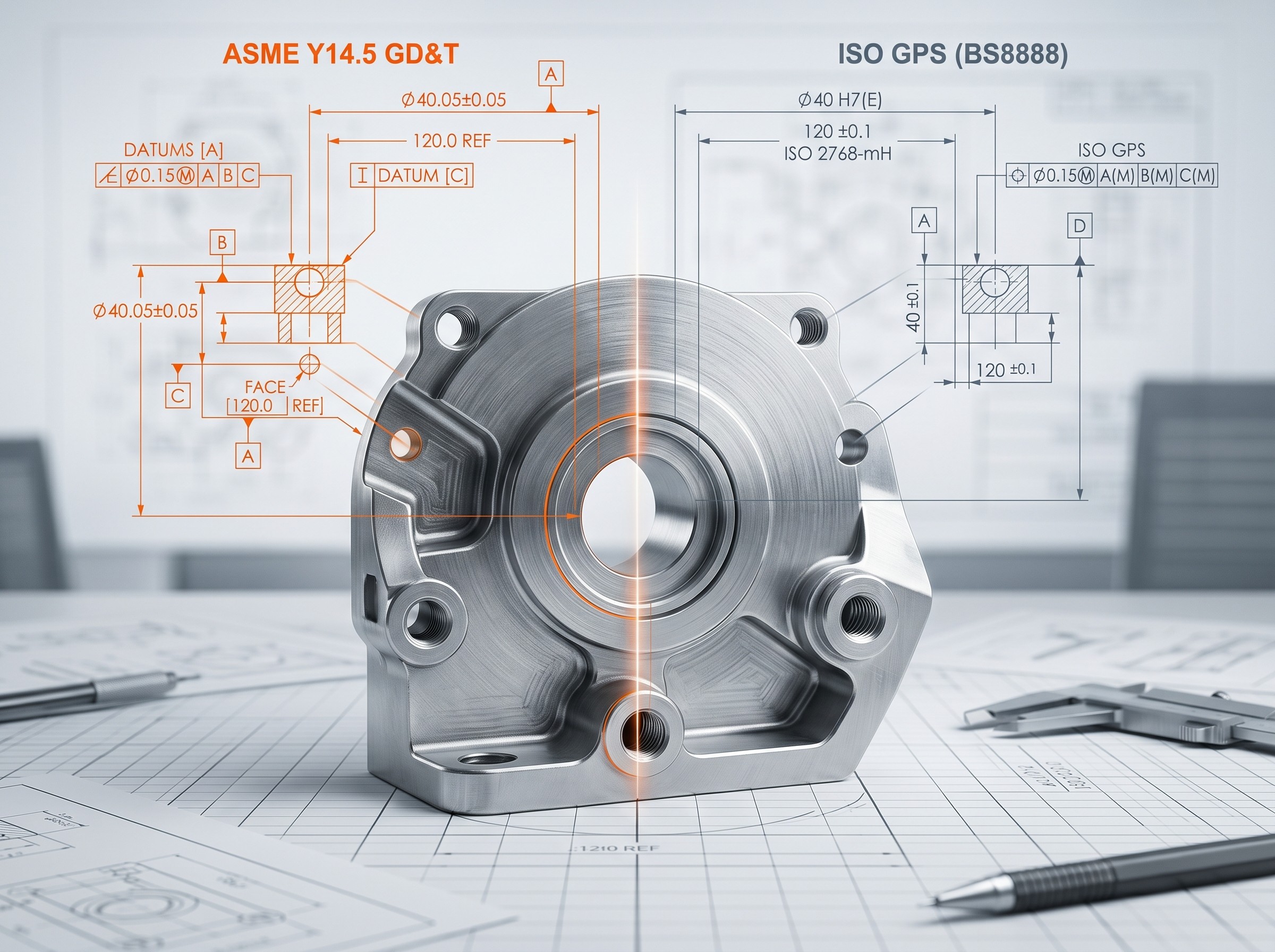
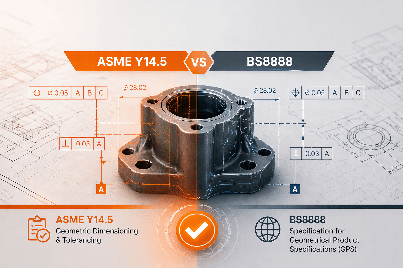
How different GD&T standards interpret the same engineering drawing — ASME Y14.5 vs BS8888.
86%of US engineering teams use ASME Y14.5 as their primary GD&T standard | 200+ISO standards consolidated inside BS8888:2025, the UK's national drawing standard | 56%of international engineering teams (outside the US) also use ASME Y14.5 | 2025BS8888 latest edition — released October 2025 with expanded MBD guidance |
Every engineering drawing you release is governed by a standard. That standard determines how every dimension is interpreted, how every tolerance zone is evaluated, and — critically — whether your supplier builds the part you intended or the part they thought you meant.
The two standards most engineering teams encounter are ASME Y14.5 (the dominant standard in the United States and North America) and BS8888 (the United Kingdom's national standard, which references and consolidates the international ISO GPS system). Understanding the differences between them is not academic. The wrong standard applied to a supplier relationship, or an undetected non-conformance against whichever standard your customer has specified, produces parts that fail inspection, contracts that fail audit, and rework that was entirely preventable.
This guide provides the most comprehensive technical comparison of ASME Y14.5-2018 and BS8888:2025 available for working mechanical engineers — including a complete symbol-by-symbol breakdown, the critical differences that cause the most manufacturing errors, and how automated GD&T compliance checking handles both standards simultaneously.
Contents
1. What is ASME Y14.5? (Current edition: 2018, reaffirmed 2024)
2. What is BS8888? (Current edition: 2025)
3. The fundamental philosophical difference — and why it matters
4. Master comparison table: 11 dimensions, side by side
5. Symbol-by-symbol comparison: where they agree and where they conflict
6. The drawing projection difference that causes mirror-image manufacturing errors
7. Limit and fit systems: ASME B4.2 vs ISO 286
8. Which standard should your team use? Decision framework
9. Working across both standards: cross-standard collaboration
10. How automated GD&T compliance checking handles both standards
11. Frequently asked questions
What is ASME Y14.5?
ASME Y14.5 is the standard published by the American Society of Mechanical Engineers (ASME) that establishes the rules, symbols, definitions, and practices for geometric dimensioning and tolerancing (GD&T) on engineering drawings and model-based definitions.
The standard traces its roots to the US military drawing standard MIL-STD-8, published in 1949 — making structured GD&T a distinctly American engineering innovation that was later adopted globally. The 1982 edition established modern GD&T practice; subsequent editions in 1994, 2009, and 2018 refined and extended it. The current edition is ASME Y14.5-2018, reaffirmed in 2024 (designated ASME Y14.5-2018 R2024).
What ASME Y14.5-2018 covers
Rules and definitions for dimensioning and tolerancing on engineering drawings and MBD models
The complete GD&T symbol set: 14 geometric characteristics covering form, orientation, location, profile, and runout
Datum reference frame establishment: primary → secondary → tertiary hierarchy
Material condition and material boundary modifiers: MMC (Ⓜ), LMC (Ⓛ), RFS, MMB, LMB, RMB
Feature control frame structure and interpretation
Rules for plus/minus tolerancing (moved to appendix in 2018, likely removed in next revision)
Model-based definition application (figures updated to include 3D model views)
Profile as the primary location tolerancing tool (emphasis increased in 2018 edition)
What changed in ASME Y14.5-2018 (vs. 2009)
Concentricity symbol (◎) removed — use position or profile for coaxiality control instead
Symmetry symbol (=) removed — use position or profile instead
Unequally disposed profile modifier (Ⓤ) formalised
Dynamic profile modifier (∿) introduced
Expanded guidance on datum reference frames and degrees of freedom
Plus/minus tolerancing moved to an appendix — likely to be removed in next revision
3D model views added throughout to support MBD workflows
Critical compliance note for teams on ASME 2009 drawings
If your drawing set was created to ASME Y14.5-2009, concentricity (◎) and symmetry (=) callouts on those drawings are valid per that edition. However, any NEW drawings must use ASME Y14.5-2018 if that is your declared standard — and ◎ and = are now non-conformant. NexCAD flags these symbols as errors on 2018-standard drawings automatically.
What is BS8888?
BS8888 is the British Standard for technical product documentation and specification, developed and published by the British Standards Institution (BSI). It is the UK's national framework standard for engineering drawings, geometric tolerancing, and product specification — and has been since it replaced the earlier BS308 standard (which was withdrawn in 2000).
BS8888 is not a standalone tolerancing system. Rather than defining its own GD&T rules, it consolidates and references over 200 international ISO standards — primarily the ISO GPS (Geometrical Product Specifications) system — into a single UK framework document. This means that when your drawing references BS8888, it is effectively referencing ISO GPS through a UK-curated lens.
The current edition is BS8888:2025, published on 30 October 2025 — the 10th edition of the standard. At 259 pages, it represents a comprehensive update with expanded guidance on model-based definition (MBD), updated general tolerance references (ISO 22081, replacing older guidance), and enhanced accessibility for engineers working in digital design environments.
What BS8888:2025 covers
Complete framework for engineering drawing conventions (projection, views, sections, drawing layout)
References to ISO GPS geometric tolerancing standards (ISO 1101 for symbols, ISO 5459 for datums, ISO 8015 for principles)
ISO 286 limit and fit system for shaft and hole fits
ISO 2768 and ISO 22081 general tolerances for linear, angular, and geometrical features
Surface texture and roughness callouts (ISO 1302, ISO 4287)
Welding symbols (ISO 2553)
Model-based definition guidance referencing ISO 16792
Updated guidance on GD&T application in CAD systems
Key standards referenced by BS8888
ISO standard | Covers | ASME equivalent |
|---|---|---|
ISO 8015 | Fundamental concepts and rules of GPS, including the Independency Principle | ASME Y14.5 Rule #1 (Envelope Principle) — opposite default |
ISO 1101 | GD&T symbols, tolerance zones, and geometric characteristic definitions | ASME Y14.5 (same scope, one document) |
ISO 5459 | Datum and datum system establishment — mathematically rigorous | ASME Y14.5 datum reference frame sections |
ISO 2692 | Maximum material requirement (MMR) and least material requirement (LMR) | ASME Y14.5 MMC (Ⓜ) and LMC (Ⓛ) modifiers |
ISO 286 | Limit and fit system: fundamental deviations, tolerance grades IT01–IT18 | ASME B4.2 (metric preferred fits) |
ISO 2768 | General tolerances for linear and angular features (referenced in title block) | Title block ± tolerance note |
ISO 22081 | General geometrical tolerances without individual specifications (BS8888:2025 update) | General note on drawing for form/orientation controls |
ISO 1302 | Surface texture indication on drawings | ASME Y14.36 surface texture |
ISO 16792 | Model-based definition: PMI on 3D CAD models | ASME Y14.41 (digital product definition) |
The fundamental philosophical difference — and why it matters
Before looking at individual symbols, rules, and applications, you need to understand the foundational philosophical difference between the two standards. This is the root cause of most cross-standard misinterpretation errors.
ASME Y14.5: The Envelope Principle (Rule #1)
ASME Y14.5 is governed by the Envelope Principle, also called Rule #1 or the Taylor Principle. This rule states that the size tolerance limits of a feature of size (a hole, shaft, pin, or slot) also control the maximum variation of that feature's form — without any additional GD&T callout being required.
Practical example: A shaft is dimensioned with a diameter of 25.00 ± 0.04 mm. Under ASME Y14.5 Rule #1, you automatically get a cylindricity control of 0.08 mm (the full size tolerance band) without needing to add a cylindricity feature control frame. The shaft cannot deviate from perfect cylindrical form by more than the size tolerance at maximum material condition.
This is powerful because it means a properly dimensioned ASME drawing can have fewer GD&T callouts while still controlling form. But it also creates a hidden constraint that engineers and suppliers must understand.
BS8888 / ISO GPS: The Independency Principle
BS8888 references ISO 8015, which establishes the Independency Principle as the default rule. This principle states the opposite: each dimension and geometric tolerance on a drawing is evaluated independently, unless a relationship is explicitly stated.
Practical example: The same shaft, dimensioned 25.00 ± 0.04 mm, per ISO 8015 carries no implicit form control. The shaft diameter must be within ±0.04 mm everywhere it is measured, but the shaft can bow, taper, or otherwise deviate from perfect cylindrical form — as long as every individual measurement of diameter is within tolerance. To control cylindricity, you must add an explicit cylindricity feature control frame.
Why this difference causes manufacturing errors
A supplier trained on ISO GPS who receives an ASME-standard drawing will not expect the implicit form control from Rule #1 — and may produce a shaft that passes their ISO-trained inspection methodology but would fail ASME inspection. Conversely, an ASME-trained engineer receiving an ISO drawing may assume implicit cylindricity control that is not present. Always declare your standard. Always ensure your supplier is trained to it.
Master comparison table: 11 key dimensions, side by side
This table compares ASME Y14.5-2018 and BS8888:2025 across every major engineering drawing dimension. Use it as your reference guide when evaluating drawings or configuring a compliance checking tool.
Topic | Standard | Detail | Practical impact |
|---|---|---|---|
Origin & governing body | ASME Y14.5-2018 (R2024) | Published by the American Society of Mechanical Engineers. Roots in US MIL-STD-8 (1949). Current edition: 2018, reaffirmed 2024. One document, 344 pages. | Single purchase, widely available training, GDTP certification programme |
Origin & governing body | BS8888:2025 | Published by BSI Group (British Standards Institution). Supersedes BS308 (withdrawn 2000). Current edition: October 2025, 259 pages. References and consolidates 200+ ISO standards. | UK's definitive reference; harmonised with ISO GPS; updated for MBD workflows |
Core philosophy | ASME Y14.5 | Envelope Principle (Rule #1): size tolerance limits control the maximum form variation of a feature. A diameter tolerance implicitly constrains cylindricity without an additional callout. | Implicit form control — fewer callouts required; can be overridden with circled-I modifier |
Core philosophy | BS8888 / ISO GPS | Independency Principle (ISO 8015): each dimensional and geometric tolerance is met independently unless a relationship is explicitly stated. Size and form are decoupled by default. | Form must be explicitly called out — more symbols required; no hidden constraints; overridden with circled-E modifier |
Document structure | ASME Y14.5 | All GD&T rules in one document (ASME Y14.5). Gauging covered separately in ASME Y14.43. | One standard to buy and reference; consistent rule set; easier to train to |
Document structure | BS8888 / ISO GPS | Over 100 interlinked ISO standards (ISO 1101 for symbols, ISO 5459 for datums, ISO 8015 for principles, ISO 2768 for general tolerances, etc.). | More mathematically rigorous; more costly and complex to implement across a team |
Drawing projection | ASME Y14.5 | Third-angle projection. Symbol: circle with truncated cone pointing right. Dominant in USA, Japan, Canada. | Confirm projection angle is declared in title block when working with international suppliers |
Drawing projection | BS8888 / ISO GPS | First-angle projection. Symbol: circle with truncated cone pointing left. Dominant in UK, Europe, most of Asia outside Japan. | Critical difference — a misread projection angle causes mirror-image manufacturing errors |
Datum reference frames | ASME Y14.5 | Primary → Secondary → Tertiary hierarchy. Datum axis derived using actual mating envelope (maximum inscribed cylinder for a hole). | Intuitive for assembly-fit tolerancing; structured for gauge design via Y14.43 |
Datum reference frames | BS8888 / ISO GPS | ISO 5459 defines datums with greater mathematical rigour, using 'simulated datum feature' concept. Datum targets and datum reference frame establishment are more explicitly specified. | More precise for CMM-based inspection; preferred in metrology-intensive environments |
GD&T symbol set | ASME Y14.5-2018 | Concentricity and symmetry symbols REMOVED in 2018 edition. Use profile or position instead. Added: dynamic profile modifier, unequally disposed profile (U). 14 geometric characteristics. | Teams on older drawings must understand legacy symbols; 2018 training now mandatory |
GD&T symbol set | BS8888 / ISO GPS | Concentricity and symmetry still in use per ISO 1101. Symbols broadly similar but some notation differences — e.g., diameter symbol leader line direction, extension line convention. | Cross-standard symbol confusion is common; always state the governing standard in the title block |
General / default tolerances | ASME Y14.5 | General tolerances defined by ± in title block note or via ASME B4.1. No equivalent to ISO 2768. | Simpler title block; engineer specifies general tolerance directly |
General / default tolerances | BS8888 / ISO GPS | ISO 2768 (linear & angular) and ISO 22081 (BS8888:2025 update) define standard tolerance classes (fine f, medium m, coarse c, very coarse v). Referenced in title block. | Concise for drawings with many features at standard tolerances; requires knowing 2768 classes |
Limit and fit systems | ASME Y14.5 | Uses inch-based ASME B4.1 fit system or metric ASME B4.2. Designation: 25H7/g6 (metric); RC, LC, FN classes (inch). | Well-established for US-centric supply chains; both metric and inch supported |
Limit and fit systems | BS8888 / ISO GPS | ISO 286 fundamental deviation system. Hole-basis H, shaft-basis h. Standard deviations A–Z (holes) / a–z (shafts) with tolerance grades IT01–IT18. | More granular than ASME; universally understood by European and Asian manufacturers |
Model-based definition (MBD) | ASME Y14.5 | Companion standard ASME Y14.41 covers MBD. ASME Y14.5-2018 includes 3D model view figures. Widely supported in SolidWorks, CATIA, NX. | Clear path for teams transitioning from 2D drawings to 3D MBD workflows |
Model-based definition (MBD) | BS8888 / ISO GPS | BS8888:2025 expands MBD guidance, referencing ISO 16792. Explicitly supports digital design environments and 3D CAD as primary source of specification. | BS8888:2025 is specifically updated for the shift to digital/MBD manufacturing |
Primary industries | ASME Y14.5 | Aerospace (NASA, Boeing, Lockheed Martin, Northrop Grumman), automotive (US OEMs: GM, Ford, Chrysler), medical device (FDA-regulated US products), defence contracts (DoD). | Required by US government contracts; expected by US Tier 1 and 2 suppliers |
Primary industries | BS8888 / ISO GPS | UK aerospace (BAE Systems, Rolls-Royce), defence (MOD contracts), automotive (UK/European OEMs), nuclear, rail, shipbuilding, medical devices (CE mark products). | Required for UK government and MOD contracts; expected by European supply chains |
Global supply chain position | ASME Y14.5 | 86% of US companies use ASME Y14.5. 56% of international companies in a 27-country survey used ASME Y14.5. Increasingly specified by US primes on global programmes. | If your customer is a US prime contractor, ASME Y14.5 is almost certainly required |
Global supply chain position | BS8888 / ISO GPS | Dominant in Europe and preferred for ISO-first global supply chains. UK manufacturing bodies specifically call for BS8888 compliance. | If your customer is UK MOD, a European OEM, or any ISO-first supply chain, BS8888/ISO GPS applies |
Symbol-by-symbol comparison
Most GD&T symbols are shared between ASME Y14.5 and ISO GPS (referenced by BS8888). The danger is in the exceptions — symbols that exist in one standard but not the other, and symbols that look the same but are interpreted differently. The red-highlighted rows below are the highest-risk differences for cross-standard engineering teams.
GD&T characteristic | ASME Y14.5 symbol | BS8888 / ISO GPS symbol | Notes on differences |
|---|---|---|---|
Flatness | ⏥ (same) | ⏥ (same) | Identical symbol and meaning in both standards |
Straightness | ⏤ (same) | ⏤ (same) | Same symbol; subtle interpretation differences re: surface vs. axis application |
Circularity (roundness) | ○ (same) | ○ (same) | Identical |
Cylindricity | ⌭ (same) | ⌭ (same) | Identical symbol; but implicit in ASME (Rule #1) vs. must be explicit in ISO |
Profile of a surface | ⌓ (same) | ⌓ (same) | ASME 2018: profile now primary location tool. ISO: similar but independency applies |
Profile of a line | ⌒ (same) | ⌒ (same) | Identical |
Parallelism | ∥ (same) | ∥ (same) | Identical |
Perpendicularity | ⊥ (same) | ⊥ (same) | Identical |
Angularity | ∠ (same) | ∠ (same) | Identical |
Position | ⊕ (same) | ⊕ (same) | Same symbol; datum derivation method differs (mating envelope vs. ISO 5459) |
Concentricity | ◎ REMOVED in 2018 | ◎ Still in use | KEY DIFFERENCE: ASME 2018 removed concentricity. Use profile or position instead. ISO 1101 retains it. Drawing with ◎ on ASME 2018 drawing = non-conformance. |
Symmetry | = REMOVED in 2018 | = Still in use | KEY DIFFERENCE: ASME 2018 removed symmetry symbol. BS8888/ISO 1101 retains it. |
Total runout | ↗↗ (same) | ↗↗ (same) | Identical |
Circular runout | ↗ (same) | ↗ (same) | Identical |
MMC / MMR modifier | Ⓜ (ASME) = Maximum Material Condition | Ⓜ (ISO) = Maximum Material Requirement | Same symbol, slightly different name. Functionally equivalent. |
LMC / LMR modifier | Ⓛ (ASME) | Ⓛ (ISO) | Same symbol, different name (Condition vs. Requirement). Functionally equivalent. |
Unequal profile | Ⓤ (ASME 2018) | UZ (ISO) | ASME uses circled U modifier; ISO uses UZ with offset value |
Dynamic profile | ∿ (ASME 2018) | Not directly equivalent | ASME 2018 addition for variable profile zones; no direct ISO counterpart |
Envelope requirement | Circled E = override to ISO's envelope | Circled E = invoke envelope (non-default) | In ISO, you need circled E to get the ASME Rule #1 equivalent |
Independency | Circled I = override Rule #1 | Default (ISO 8015) | In ASME, you need circled I to get ISO's independency. In ISO it is the default. |
The concentricity and symmetry trap — most common cross-standard error
The removal of concentricity (◎) and symmetry (=) from ASME Y14.5-2018 is the single most common source of cross-standard GD&T non-conformances in 2025–2026. Engineering teams transitioning from Y14.5-2009 to Y14.5-2018 frequently retain these symbols. Suppliers receiving an ASME 2018 drawing with ◎ have no valid interpretation. NexCAD's AI drawing checker flags both symbols automatically as non-conformant when reviewing against ASME Y14.5-2018, and accepts them as valid when reviewing against BS8888 / ISO GPS.
The drawing projection difference that causes mirror-image manufacturing errors
This is the drawing convention difference with the most catastrophic manufacturing consequences: the difference between first-angle and third-angle projection.
Third-angle projection (ASME Y14.5 / USA)
In third-angle projection, each view is placed on the same side of the part as the direction you are looking. Looking at the front of a part, the top view appears above the front view, the right view appears to the right, and so on. The view placement is intuitive — views go where you would expect them if you unfolded the part. The third-angle projection symbol shows a truncated cone with the small end pointing toward the viewer (on the right).
First-angle projection (BS8888 / ISO / UK & Europe)
In first-angle projection, each view is placed on the opposite side of the part from the direction you are looking. Looking at the front of a part, the top view appears below the front view, the right view appears to the left. The first-angle projection symbol shows a truncated cone with the small end pointing away from the viewer (on the left).
Mirror-image manufacturing error — real consequence
A machinist reading a drawing without checking the projection symbol — or a team that fails to declare the projection angle in the title block — can produce a mirror image of the intended part. Left becomes right. Top becomes bottom. For complex parts with asymmetric features, this is a complete scrap event. BS8888:2025 and ASME Y14.5-2018 both require the projection symbol to appear in the title block. NexCAD checks for projection symbol presence and flags its absence as a critical error.
Limit and fit systems: ASME B4.2 vs ISO 286
When you specify a fit between mating parts — a shaft running in a bearing, a pin in a hole, a bushing press-fitted into a housing — the standard you use determines how that fit is called out on the drawing and how it is manufactured and inspected.
ASME fit system (B4.1 / B4.2)
ASME B4.1 covers inch-based preferred limits and fits, using named classes: RC (running clearance), LC (locational clearance), LT (locational transition), LN (locational interference), FN (force and shrink fits). ASME B4.2 covers metric preferred limits and fits, using a simplified set of preferred fits expressed as letter/number combinations in a hole-basis system (H7/f6, H7/k6, H7/p6 etc.).
ISO 286 fit system (referenced by BS8888)
ISO 286 defines the international standard for limits and fits. It uses a systematic notation: fundamental deviation letter (A–Z for holes, a–z for shafts) combined with an International Tolerance (IT) grade (IT01 through IT18). The hole-basis system uses H for the hole; the shaft-basis system uses h for the shaft.
Example: 25 H7/g6 specifies a 25 mm nominal size, H7 hole (fundamental deviation H, IT grade 7), g6 shaft (fundamental deviation g, IT grade 6) — a standard clearance running fit. This notation is universal to ISO 286 and understood by any European or Asian manufacturer.
Fit type | ASME B4.2 (metric) | ISO 286 (BS8888) |
|---|---|---|
Loose running clearance | H11/c11 | H11/c11 — same |
Free running clearance | H9/d9 | H9/d9 — same |
Close running clearance | H8/f7 | H8/f7 — same |
Sliding fit | H7/g6 | H7/g6 — same |
Locational clearance | H7/h6 | H7/h6 — same |
Locational transition | H7/k6 | H7/k6 — same |
Locational interference | H7/p6 | H7/p6 — same |
Medium drive fit | H7/s6 | H7/s6 — same |
Force fit | H7/u6 | H7/u6 — same |
Note: For metric fits, ASME B4.2 and ISO 286 use the same preferred fit designations. The practical difference is primarily in the inch-based ASME B4.1 system, which has no ISO equivalent. If your team works in metric, the fit designations are compatible between the two standards — but the drawing must declare which standard governs to avoid ambiguity on non-standard fit callouts.
Which standard should your team use? Decision framework
There is no universally correct answer. The right standard for your team depends on four factors: your customer geography, your supplier geography, your industry, and your regulatory environment. The table below maps the most common engineering team situations to the recommended standard.
Your situation | Recommended standard | Why |
|---|---|---|
US-based team, US customers and suppliers | ASME Y14.5-2018 | Dominant in North America. Required by US DoD and most US prime contractors. |
UK-based team, UK MOD or defence supply chain | BS8888:2025 | Required for UK MOD contracts. BSI-supported. ISO GPS harmonised. |
European supply chain (DE, FR, IT, ES) | ISO GPS (BS8888 ref) | ISO GPS dominates Europe. BS8888 is the UK implementation of ISO GPS. |
Global supply chain, US prime customer | ASME Y14.5-2018 | US primes typically specify ASME. Confirm with customer's drawing standard. |
Global supply chain, EU/UK prime customer | BS8888 / ISO GPS | European primes typically require ISO GPS. Confirm with contract. |
Team using both US and EU suppliers | Declare both | State governing standard clearly in title block. Train to both. Use AI checker that supports both. |
New product company, no legacy drawing set | Either — pick one | Choose based on your target customer geography. Commit to one and enforce it consistently. |
Aerospace (commercial, US-registered aircraft) | ASME Y14.5 | FAA-regulated programmes typically specify ASME. Boeing, Airbus US primes: ASME. |
Aerospace (UK/EU-registered aircraft, EASA regulated) | BS8888 / ISO GPS | Rolls-Royce, BAE Systems, Airbus EU programmes: BS8888 / ISO GPS. |
Medical device (FDA 510k / PMA) | ASME Y14.5 | FDA-regulated products: US standards expected. ISO 13485 QMS still compatible. |
Medical device (CE mark, UK CA mark) | BS8888 / ISO GPS | CE/UKCA compliance: European drawing standards. BS8888 aligns with ISO 9001. |
The one rule that overrides everything
Always follow what your customer specifies
If your customer's contract, drawing requirements document (DRD), or supplier quality requirements (SQR) specifies a standard, that is the standard you use — regardless of what your team prefers internally. Compliance with the customer-specified standard is a contractual requirement. Non-compliance is grounds for rejection of your first article, failure of your supplier audit, and potentially loss of the contract.
Working across both standards: cross-standard collaboration
Global supply chains mean that engineering teams increasingly need to work with both ASME Y14.5 and BS8888/ISO GPS simultaneously — a US prime contractor with European Tier 2 suppliers, or a UK company bidding on US defence programmes.
The five rules for cross-standard success
Always declare the governing standard in the title block. Every drawing must state 'Interpreted per ASME Y14.5-2018' or 'Interpreted per BS8888:2025' explicitly. Never leave this ambiguous.
Train your team to both standards. Engineers and inspectors who work with suppliers on both standards need formal training in the interpretation differences — particularly the Envelope vs. Independency Principle and the removed symbols (◎ and =).
Brief your suppliers on your standard. Do not assume a supplier in a different country knows your drawing standard. Include a drawing standard reference in your supplier quality requirements.
Use AI compliance checking that supports both standards simultaneously. Manual checking of cross-standard compliance is error-prone. A tool like NexCAD that can apply ASME Y14.5-2018 rules to one drawing set and BS8888:2025 rules to another — flagging the correct non-conformances for each — eliminates the risk of applying the wrong standard's rules.
When in doubt, add explicit callouts. If there is any risk that a supplier might interpret your drawing under the wrong standard's default rules, add explicit callouts rather than relying on defaults. An explicit cylindricity callout is understood identically under both ASME and ISO. The implicit ASME Rule #1 form control is not.
How automated GD&T compliance checking handles both standards
Manual GD&T compliance checking is one of the most demanding aspects of engineering drawing review — and the one most vulnerable to the cross-standard errors described in this article. A reviewer who has been trained to ASME Y14.5 and has spent their career on ASME drawings will make systematic errors when reviewing a BS8888 drawing, and vice versa.
NexCAD's AI drawing checker validates drawings against both ASME Y14.5-2018 and BS8888:2025 / ISO GPS, applying the correct rule set for each standard automatically based on the declared standard in the drawing's title block. Here is what that means in practice:
Check category | What NexCAD validates (ASME Y14.5) | What NexCAD validates (BS8888 / ISO GPS) |
|---|---|---|
Concentricity / symmetry | Flags ◎ and = symbols as non-conformant (removed in 2018 — must use position or profile) | Accepts ◎ and = as valid. Checks for correct ISO application per ISO 1101. |
Rule #1 / Envelope | Validates that no explicit form callout is missing where Rule #1 is overridden (circled I present) | Flags features of size that lack either explicit form callout or circled-E, per independency principle |
General tolerances | Checks ± title block tolerance format and consistency | Checks ISO 2768 class declaration and validates feature tolerances against declared class (f/m/c/v) |
Projection angle | Validates third-angle projection symbol in title block | Validates first-angle projection symbol in title block |
Datum reference frame | Checks three-plane hierarchy completeness (primary → secondary → tertiary) per Y14.5 | Checks datum establishment per ISO 5459 principles |
Profile tolerance | Validates ASME profile as primary location tool (2018). Checks Ⓤ modifier format. | Validates ISO profile callouts. Checks UZ offset notation. |
Feature control frame format | Validates ASME FCF structure: characteristic | tolerance | modifiers | datums | Validates ISO FCF structure with compartment notation differences |
Limit & fit system | Checks ASME B4.1/B4.2 fit designations if present | Checks ISO 286 fundamental deviation letters and IT grades |
Standards declaration | Confirms 'ASME Y14.5-2018' stated in title block notes | Confirms 'BS8888:2025' or relevant ISO standards stated in title block |
Why this matters operationally
An engineering team that regularly receives drawings from both US and European suppliers — or that submits drawings to both US and EU customers — cannot maintain a single internal GD&T mental model. The Envelope vs. Independency difference alone creates systematic inspection failures. AI compliance checking that understands both standards eliminates the need for your engineers to context-switch between rule sets on every drawing they review.
Frequently asked questions
Is BS8888 the same as ISO GPS?
Not exactly — BS8888 is the UK's national implementation of ISO GPS, not a separate standard. BS8888 references and consolidates over 200 ISO GPS standards (ISO 1101, ISO 5459, ISO 8015, ISO 286, and others) into a single UK framework document. Following BS8888 means following ISO GPS as curated and structured for UK industry. The BSI updates BS8888 as the underlying ISO standards are revised — the 2025 edition incorporates ISO changes published since 2020.
Which standard do Boeing and Airbus use?
Boeing (US prime) predominantly uses ASME Y14.5 for its drawing standard, consistent with its US base and US DoD contracts. Airbus is more complex: Airbus SE (European) uses ISO GPS / BS8888-aligned standards for its European programmes, while Airbus's US operations (Airbus Americas) often work to ASME Y14.5. Boeing's supply chain — whether in the US, UK, or elsewhere — is typically required to comply with ASME Y14.5 as specified in Boeing's supplier quality requirements.
Can I mix ASME Y14.5 and ISO GPS callouts on the same drawing?
No. Mixing symbols from different standards on the same drawing creates an irreconcilable interpretation problem. Concentricity (◎), which is valid in ISO 1101 but removed from ASME Y14.5-2018, is the most common example of accidental mixing. Your drawing must be governed by one standard, declared in the title block, and all callouts must conform to that single standard. If you need a callout that exists in one standard but not the other, use the equivalent callout that the governing standard provides.
Do my suppliers need to be trained to the same standard as my drawing?
Yes — this is essential, not optional. A supplier who inspects your ASME Y14.5 drawing using ISO GPS interpretation rules will evaluate tolerances differently, potentially accept parts that would fail your inspection, and reject parts that would pass. At minimum, your supplier quality requirements must reference the governing drawing standard, and you should confirm that your supplier's quality engineering staff are trained to it. For high-volume or safety-critical supply relationships, verification of supplier GD&T competence at the appropriate standard level is standard practice.
What version of ASME Y14.5 should I be using in 2026?
ASME Y14.5-2018 (reaffirmed 2024, designated R2024) is the current edition and the one you should reference on all new drawings. ASME Y14.5-2009 is still legally valid for drawings created under that edition, but should not be used on new drawings. The 2018 edition's most significant change — the removal of concentricity and symmetry — means any drawing with those symbols must declare 2009 (or earlier) as its governing edition, or the callout is non-conformant.
What version of BS8888 is current?
BS8888:2025, published 30 October 2025, is the current edition. This is the 10th edition of the standard. It incorporates updated guidance on MBD (ISO 16792), updated general tolerance references (ISO 22081), and enhanced accessibility across the standard's structure. Teams on BS8888:2020 should plan to update their title block standard reference and review for any changes that affect their drawing practices.
How does NexCAD know which standard to apply to my drawing?
NexCAD reads the standard declaration in your drawing's title block — 'ASME Y14.5-2018', 'BS8888:2025', or a specific ISO standard reference. The AI then applies the rule set for that standard automatically: flagging ◎ and = as errors on ASME 2018 drawings, accepting them on BS8888 drawings; checking for the Envelope Principle on ASME drawings and the Independency Principle defaults on ISO drawings; validating the projection symbol against the declared standard. If no standard is declared in the title block, NexCAD flags the missing declaration itself — because an undeclared standard is itself a non-conformance.
Is there an international standard that supersedes both ASME Y14.5 and BS8888?
Not in the sense of a single universal GD&T document. ISO GPS is the closest thing to a universal international tolerancing system — BS8888 references it directly. However, ASME Y14.5 remains the dominant standard in North America and on US-primed global programmes. The ISO GPS and ASME Y14.5 standards continue to evolve independently, with occasional harmonisation efforts but no immediate convergence. For the foreseeable future, engineering teams working globally need to understand and work with both.