

NexCAD
Introduction
Every mechanical assembly is built around a simple question: How should two mating parts fit together? Whether you're designing a gearbox, assembling a bearing, manufacturing an automotive component, or creating a precision aerospace mechanism, the relationship between a shaft and its mating hole determines how the assembly performs throughout its life. If the fit is too loose, components may vibrate, wear prematurely, or lose alignment. If the fit is too tight, assembly becomes difficult, excessive stresses develop, and components may fail before reaching their intended service life. Selecting the correct engineering fit is therefore one of the most important decisions a design engineer makes.
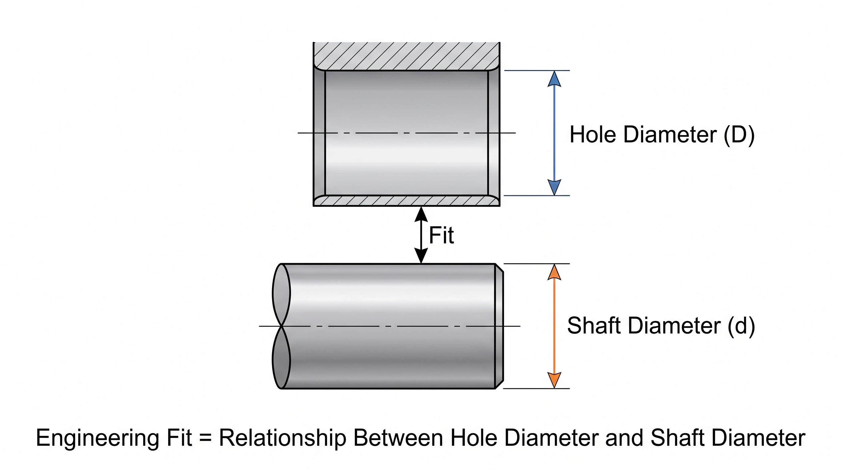
Figure 1. An engineering fit describes the dimensional relationship between a hole and its mating shaft. The difference between their manufactured sizes determines whether the assembly results in a clearance, transition, or interference fit.
What Is an Engineering Fit?
An engineering fit describes the relationship between two mating components after manufacturing.
Most commonly, these components are:
A cylindrical shaft
A cylindrical hole
Although both parts are designed using the same nominal diameter, manufacturing tolerances mean neither component is produced at exactly the same size every time.
Instead, each part is allowed to vary within a specified tolerance range.
The relationship between these two tolerance zones determines the final fit.
In simple terms:
Fit = Hole Size − Shaft Size
Depending on the resulting difference, the assembly may have:
Positive clearance
Zero clearance
Negative clearance (interference)
This determines how easily the components assemble and how they behave during operation.
Why Engineering Fits Matter?
Engineering fits influence almost every aspect of a product's performance.
Choosing the wrong fit can result in:
Excessive vibration
Bearing failure
Poor positional accuracy
Difficult assembly
Increased manufacturing costs
Noise during operation
Premature wear
Reduced product lifespan
Conversely, selecting the appropriate fit ensures:
Reliable assembly
Controlled movement
Accurate positioning
Efficient load transfer
Longer service life
Reduced maintenance
For this reason, fit selection is considered a fundamental part of Design for Manufacturability (DFM).
Where Are Engineering Fits Used?
Engineering fits are found in virtually every mechanical product.
Some common examples include:
Application | Typical Fit Type |
|---|---|
Rolling bearings | Interference or Transition |
Electric motors | Interference |
Gear hubs | Interference |
Sliding guide rods | Clearance |
Hydraulic cylinders | Clearance |
Linear bearings | Clearance |
Precision locating pins | Transition |
Machine tool spindles | Transition |
Bushings | Clearance |
Automotive wheel hubs | Interference |
Understanding Nominal Size and Tolerances
One of the most common misconceptions among new engineers is believing that a dimension on a drawing represents the exact manufactured size.
In reality, manufacturing processes always introduce small dimensional variations.
Consider a shaft specified as:
The finished shaft may actually measure:
24.998 mm
24.995 mm
25.003 mm
depending on the manufacturing process and specified tolerance.
Similarly, the mating hole may vary slightly around its nominal diameter.
This is why engineering standards define allowable tolerance zones rather than single fixed dimensions.
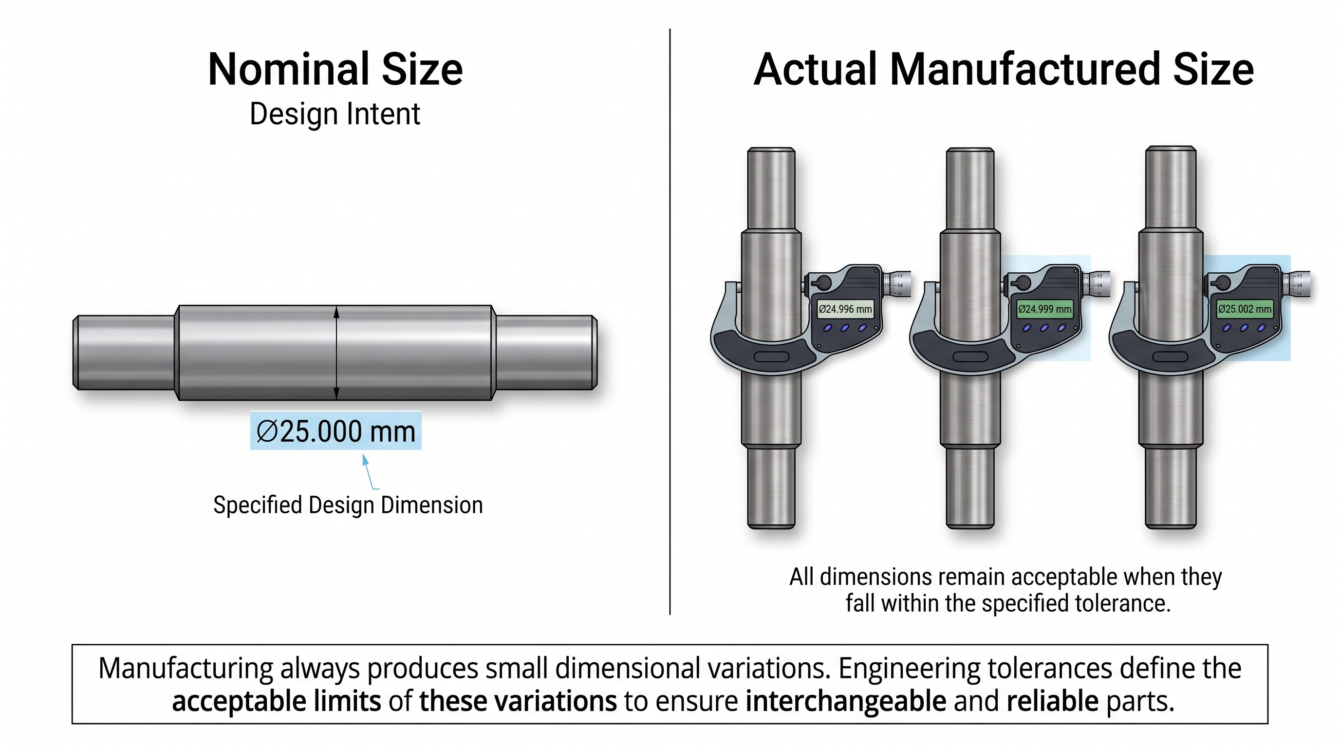
Figure 2. A nominal size is the intended design dimension, while actual manufactured components vary slightly due to production processes. Engineering tolerances define the acceptable range of variation to ensure parts remain functional and interchangeable.
How ISO 286 Defines Engineering Fits
Rather than specifying an exact diameter for every component, engineers use the ISO 286 system of limits and fits, an internationally recognized standard for defining permissible dimensional variations.
ISO 286 assigns:
Letters to indicate the position of the tolerance zone relative to the nominal size.
Uppercase letters (A–ZC) are used for holes.
Lowercase letters (a–zc) are used for shafts.
Numbers to indicate the tolerance grade (IT grade), which defines the width of the tolerance zone.
A fit is created by combining a hole designation with a shaft designation. For example:
H7/g6 – Precision clearance fit
H7/h6 – Close running fit
H7/k6 – Transition fit
H7/p6 – Interference fit
Each combination produces a predictable relationship between the hole and shaft, enabling interchangeable parts and consistent manufacturing across suppliers.

Figure 3. ISO 286 defines tolerance zones relative to the nominal size. By combining a hole tolerance (uppercase letters) with a shaft tolerance (lowercase letters), engineers create a clearance, transition, or interference fit depending on the relative positions of the two zones.
Types of Engineering Fits
Engineering fits are classified into three primary categories based on the dimensional relationship between the hole and the shaft after manufacturing.
Each type is designed for a specific purpose, balancing ease of assembly, positional accuracy, and the ability to transmit loads or motion.
Understanding when to use each fit is essential for creating reliable, manufacturable, and cost-effective mechanical designs.
The three main categories are:
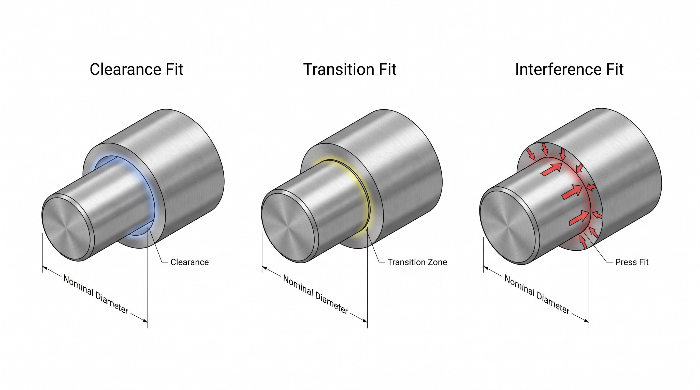
Clearance Fit – The shaft is always smaller than the hole, allowing free movement or easy assembly.
Transition Fit – The shaft and hole are nearly the same size, resulting in either a slight clearance or slight interference depending on manufacturing tolerances.
Interference Fit – The shaft is intentionally larger than the hole, requiring force or thermal methods during assembly to create a secure, permanent connection.
The following sections explain each fit type in detail, including how it works, where it is commonly used, its advantages and disadvantages, and typical ISO 286 fit designations.
Clearance Fits
A clearance fit ensures the shaft is always slightly smaller than the mating hole, creating a positive gap after manufacturing. This guaranteed clearance allows components to slide or rotate freely without requiring force during assembly. Because of their reliability and ease of manufacturing, clearance fits are the most widely used fit type in mechanical engineering.
Typical applications include linear guide rods, hydraulic cylinders, conveyor rollers, bushings, and removable machine components where smooth movement or frequent maintenance is required.
Common ISO 286 combinations include H7/g6, H8/f7, and H9/d9, each offering different amounts of clearance depending on the required precision.
While clearance fits simplify assembly and maintenance, they are not suitable where maximum positional accuracy or torque transmission is required.
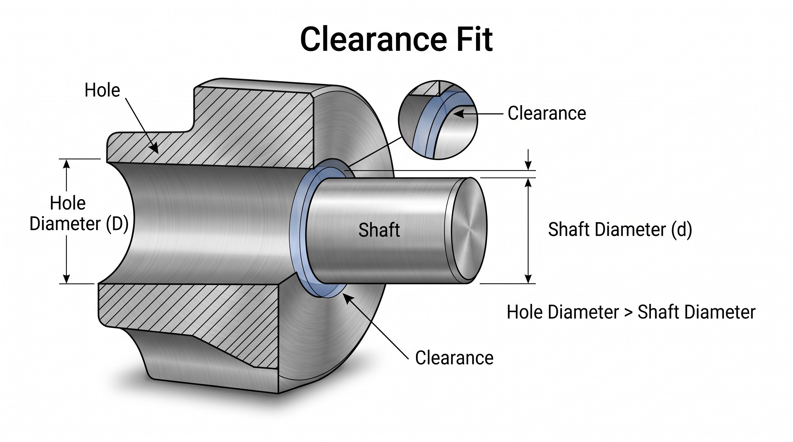
Figure 4. In a clearance fit, the shaft is always smaller than the hole, creating a positive gap that allows free movement and easy assembly.
Transition Fits
A transition fit is an engineering fit where the shaft and the mating hole are manufactured to nearly identical dimensions. Depending on the actual sizes produced within the specified tolerances, the assembly may result in either a slight clearance or a slight interference. This balance provides accurate positioning while still allowing components to be assembled or disassembled with minimal force in most cases.
Transition fits are commonly used in assemblies that require precise alignment without creating a permanent joint. Typical applications include locating pins, gear hubs, couplings, bearing assemblies, precision machine tools, and automotive transmission components where accurate positioning is critical but future maintenance or replacement may still be required.
Common ISO 286 combinations include H7/k6, H7/js6, and H7/m6, each providing varying degrees of transition depending on the required balance between assembly ease and positional accuracy.
While transition fits offer improved alignment and reduced play compared to clearance fits, they may require light pressing or tapping during assembly and are generally less suitable for applications requiring frequent disassembly.
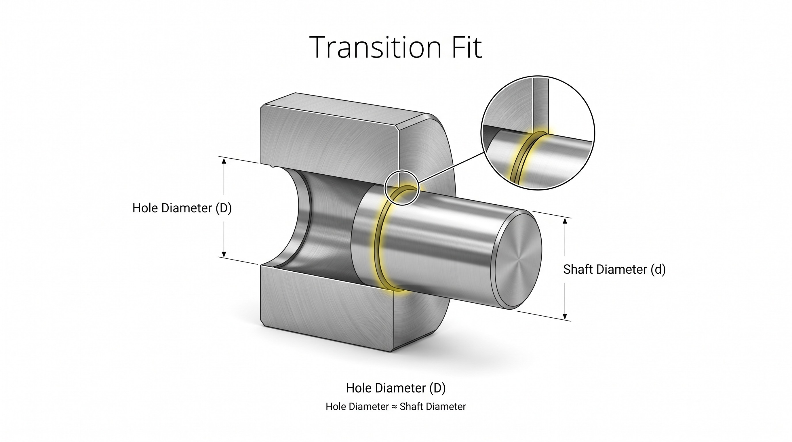
Figure 5. A transition fit provides a very close fit where slight clearance or slight interference may occur depending on manufacturing tolerances.
Interference Fits
An interference fit, also known as a press fit, is an engineering fit in which the shaft is intentionally manufactured slightly larger than the mating hole. This creates a negative clearance, requiring force, hydraulic pressing, or thermal expansion methods such as shrink fitting during assembly. Once assembled, the interference between the two components forms a rigid, high-strength connection capable of transmitting significant loads and torque without relative movement.
Interference fits are widely used in applications where a secure, permanent connection is essential. Common examples include bearing races, gear hubs, flywheels, railway wheels, pulleys, electric motor rotors, and heavy-duty industrial machinery where components must remain firmly fixed under high loads or continuous operation.
Common ISO 286 combinations include H7/p6, H7/s6, H7/u6, and H7/x6, with increasing levels of interference selected according to the required holding force and operating conditions.
Although interference fits provide exceptional rigidity, accuracy, and torque transmission, they typically require specialized assembly methods and make maintenance or component replacement more difficult due to the permanent nature of the joint.
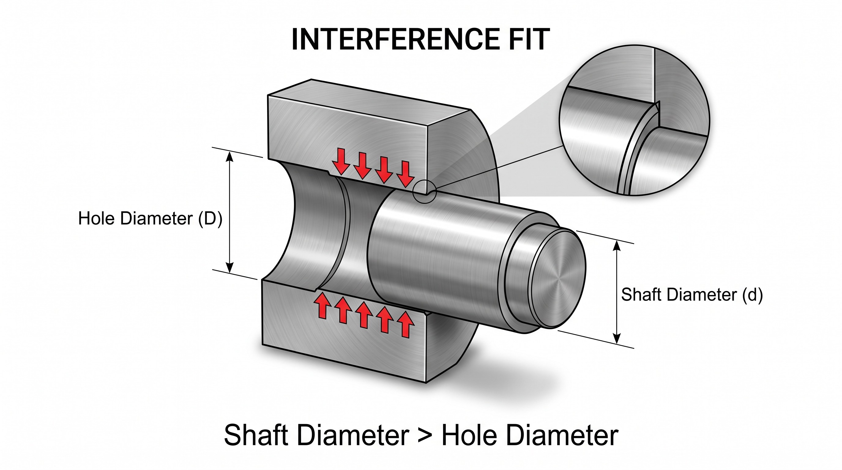
Figure 6. An interference fit creates a secure mechanical joint by making the shaft slightly larger than the hole, requiring force or thermal assembly methods.
Comparison
Feature | Clearance | Transition | Interference |
|---|---|---|---|
Assembly | Easy | Light Force | Press Fit |
Movement | Yes | Limited | None |
Maintenance | Easy | Moderate | Difficult |
Accuracy | Medium | High | Very High |
Torque Transmission | Low | Medium | High |
Typical Uses | Bearings, Bushings | Gears, Couplings | Flywheels, Hubs |
Choosing the Right Engineering Fit
Selecting the right engineering fit depends on how the components will function throughout their service life. The correct choice balances ease of assembly, required movement, positional accuracy, load transmission, maintenance requirements, and manufacturing cost. Rather than selecting the tightest fit possible, engineers should choose the fit that best supports the application's performance and reliability.
Consider the following questions when selecting a fit:
Does the component need to slide or rotate freely?
Choose a Clearance Fit for applications requiring smooth movement, easy assembly, or regular maintenance.Is accurate positioning required while allowing future disassembly?
Choose a Transition Fit when components need precise alignment with minimal play but may still require servicing or replacement.Does the assembly require a permanent, high-strength connection?
Choose an Interference Fit when components must remain securely fixed and transmit high loads or torque without movement.
Other factors such as operating temperature, lubrication, material properties, manufacturing capability, and expected wear should also be considered, as they can influence the long-term performance of the selected fit.
Tip: Always refer to ISO 286 tolerance standards when specifying engineering fits to ensure consistency, interchangeability, and manufacturability across suppliers and production facilities.
Conclusion
Engineering fits are a fundamental part of mechanical design, determining how shafts and holes interact once components are manufactured and assembled. Whether a design requires smooth movement, precise positioning, or a permanent mechanical connection, selecting the appropriate fit is essential for ensuring performance, reliability, and ease of manufacturing.
Understanding the differences between clearance, transition, and interference fits allows engineers to make informed design decisions, reduce assembly issues, minimize wear, and improve product longevity. By combining the right fit with appropriate manufacturing tolerances defined by ISO 286, designers can create assemblies that are both functional and cost-effective.
As engineering products become more complex, validating fit selections early in the design process helps prevent costly manufacturing errors and reduces the need for design revisions. Using modern engineering validation tools alongside internationally recognized standards enables teams to deliver more accurate, reliable, and manufacturable designs with confidence.
Validate Engineering Fits with Confidence
Selecting the correct fit is only one part of creating a manufacturable design. NexCAD helps engineers review technical drawings, verify dimensional tolerances, identify potential manufacturability issues, and improve design quality before production begins.
Explore NexCAD's AI-powered engineering validation tools to streamline your design review process and reduce costly manufacturing errors.